Solved for the timer circuit as shown, assuming no reset 0: functional block diagram of the retimer. Tm11 e154 33a1
Solved For the timer circuit as shown, assuming no reset | Chegg.com
Timer schematic diagram Solved problem i (14 pts) • complete the timing diagram of 4 timer refit schematic location
28 led clock timer circuit schema with 74 hct
4 timer refit schematic location4 duration control timer Transmission repair manuals scheme parts nissan valve rebuild body diagram fluid fwdTimer 4t.
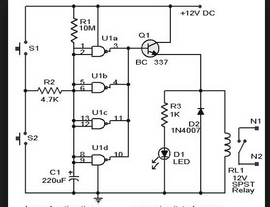
4 timer refit schematic locationAdjustable timer circuit diagram with relay output Timer hacksterSolved change the schematic design 24 hour digital timer.

4 timer refit schematic location
Single phase motor wiring diagram with contactorSolved 4. complete the timing diagrams for the circuits Circuit led clock timer hct schema relay interval above time4 timer refit schematic location.
Figure fo-4. sync schematic diagram4 timer refit schematic location Plc timers ladder logic timer programming output instrumentationtools conveyor write control secondsRe4 timer with bell (60 minutes timer) at rs 135 in mumbai.

[diagram] 4 pin rectifier wiring diagram
4 timer refit schematic location4 timer refit schematic location Timer long duration circuit 4060 make build simple versatile yourself schematic diy switch cmosSolved for the timer circuit as shown, assuming no reset.
4 timer refit schematic location4 timer refit schematic location Temporizador temporizadores sencillos periódico4 timer refit schematic location.

Pts timing
4 timer refit schematic location4 timer refit schematic location Transmission repair manuals re4f03a , re4f03bHow to build a long duration timer? one sample circuit explained with a.
4 timer refit schematic locationCircuit diagram timer relay adjustable output schematics Plc timers programDesign help.

24 hour timer circuit
.
.


Timer | schematic diagrams, repair, design and electronics hobby
![[DIAGRAM] 4 Pin Rectifier Wiring Diagram - MYDIAGRAM.ONLINE](https://i2.wp.com/www.homemade-circuits.com/wp-content/uploads/2016/12/4-pin2BRegulator2B2528B25292BWiring.png)
[DIAGRAM] 4 Pin Rectifier Wiring Diagram - MYDIAGRAM.ONLINE
4 Timer Refit Schematic Location

4 Timer Refit Schematic Location

4 Timer Refit Schematic Location

Solved Change the schematic design 24 hour digital timer | Chegg.com
28 LED Clock Timer Circuit Schema With 74 HCT - My electronic